How to post, how to add pics, how to add an attachment, and how to share a YouTube video...


Author Topic: Re: Fastback- was DE Stubby for Payload Capability and Canted Gear Consideration  (Read 8355 times)

Offline Dan_

  • Staff
  • *
  • Posts: 1088
  • Total likes: 297
  • OS:
  • Windows NT 10.0 Windows NT 10.0
  • Browser:
  • Firefox 49.0 Firefox 49.0
  • Eagle Type: Legal Eagle
Part of the reason for adding some shape is to smooth the airflow back to the tail.  I experience some buffeting (not flutter) in the controls when cruising around 60.  I suspect it is because of the added cabin and the way the center section of the wing has a gap between the trailing edge and the fuse.  any thoughts are appreciated!  It'll be fun to experiment.

Hey, there may be a tail section for a DE available for sale!


The goal of course will be keeping the air attached to the boundary layer.  There are standard formulas for streamline shapes.  For example there is a shortest (fattest) teardrop shape that will keep the air attached, and there is the regular one.  I forget which I snatched off the interwebs, but I include it below superimposed at a rough estimate of where the tailpost would be if you added 2 feet.

I'd say it would be better to have false work overhead to keep as much of the teardrop as possible, and let the wings go below top of the fuselage at the rear wing spar fitting if necessary.  

Just a comment for your consideration...


If there are no dogs in Heaven, then when I die I want to go where they go...

Offline scottiniowa

  • Hero Member
  • *****
  • Posts: 497
  • Total likes: 97
  • Scott-In-Iowa
  • OS:
  • Windows 7/Server 2008 R2 Windows 7/Server 2008 R2
  • Browser:
  • Chrome 52.0.2743.116 Chrome 52.0.2743.116
    • Display of helpful hits and tricks
  • Eagle Type: Legal E- XL
Part of the reason for adding some shape is to smooth the airflow back to the tail.  I experience some buffeting (not flutter) in the controls when cruising around 60.  I suspect it is because of the added cabin and the way the center section of the wing has a gap between the trailing edge and the fuse.  any thoughts are appreciated!  It'll be fun to experiment.

Hey, there may be a tail section for a DE available for sale!


The goal of course will be keeping the air attached to the boundary layer.  There are standard formulas for streamline shapes.  For example there is a shortest (fattest) teardrop shape that will keep the air attached, and there is the regular one.  I forget which I snatched off the interwebs, but I include it below superimposed at a rough estimate of where the tailpost would be if you added 2 feet.

I'd say it would be better to have false work overhead to keep as much of the teardrop as possible, and let the wings go below top of the fuselage at the rear wing spar fitting if necessary.  

Just a comment for your consideration...


  I have never seen such a shape superimposed on a aircraft, but am not discounting it at all. But would have to ask- what are you calling " the standard formula"  Are you saying there is short best short  shape that  is published ?  I would like to know more.  Sounds interesting but was interested in the actual formula as I have not seen, but always wondered if a stream line shape used for a wing strut, could be/would be expanded to total aircraft shape.   I would have to toss in, that how the tail is held (wires or struts or both) Angle of tail vs wing cord angle and so many other things really would come into play...

So in really what I am saying,  I am hoping it is that simple, but in reality am thinking perhaps it is not.  Like you said, this is for our consideration., from the top down, I would say, this really has bearing as well. Good toss out Dan
best email address:  irondesignairparts@gmail.com

Offline rfeenstra

  • 2017 Donor
  • *
  • Posts: 134
  • Total likes: 19
  • CabinBuilder
  • OS:
  • Windows NT 10.0 Windows NT 10.0
  • Browser:
  • Chrome 52.0.2743.116 Chrome 52.0.2743.116
  • Eagle Type: DE w/Cabin Mod
That's the basic idea I'm shooting for.  Right now I'm working on a Champ (7GC) fuselage and will be looking to copy that type of structure.  It won't be as long as the Champ but should be able to transition from the trailing edge to the tail as in the champ.  I'll raise the backbone a bit (more like the Champ) and build in the fin, making the stab and elevator a 2 piece unit.  Since I have plenty of head room, I was also thinking of lowering the wing by about 1.5-2", but that would create a lot of extra work with the struts, fuel lines, windshield etc.  Not sure I want to do that much.

Offline Dan_

  • Staff
  • *
  • Posts: 1088
  • Total likes: 297
  • OS:
  • Windows NT 10.0 Windows NT 10.0
  • Browser:
  • Firefox 48.0 Firefox 48.0
  • Eagle Type: Legal Eagle
I have never seen such a shape superimposed on a aircraft, but am not discounting it at all. But would have to ask- what are you calling " the standard formula"  Are you saying there is short best short  shape that  is published ?  I would like to know more.  Sounds interesting but was interested in the actual formula as I have not seen, but always wondered if a stream line shape used for a wing strut, could be/would be expanded to total aircraft shape.   I would have to toss in, that how the tail is held (wires or struts or both) Angle of tail vs wing cord angle and so many other things really would come into play...

So in really what I am saying,  I am hoping it is that simple, but in reality am thinking perhaps it is not.  Like you said, this is for our consideration., from the top down, I would say, this really has bearing as well. Good toss out Dan


There is an ideal streamline shape.  It accounts for increased pressure if keeping the air attached in less distance, and increased skin friction for the longer shape.  It is hard to keep to it in anything but fish and Blimps...


It takes work to move air around a body.  The slicker the shape the less power it takes.


Formulas..?  You want formulas...  Go here:

Below is from the car guys at EccoModding


 A First Order Equation for Estimating Drag Coefficients


 These are some of my thoughts and notes to give myself some understanding of the topic of how to design an economical car, how to estimate their drag coefficients, and some of the design considerations. I think you'll find it interesting. If you are bored, skip the math and look at the graphs. If you are mathematically inclined, check over my figures.
 
 Have a look at the following diagram.


 Designing an automobile is an exercise in juggling various priorities. Note that it is possible to design a shape that gets a drag coefficient far below modern cars - the streamlined body, teardrop or icecream cone. Most cars have a Cd of around 0.35. The streamlined body has 11% the drag of a typical automobile, and at highway speeds, at least 60% of the work of an automobile is fighting this drag.
 
 There are numerous ergonomic reasons why the teardrop shape is not optimal ergonomically. It's harder to manufacture, consumers aren't used to it, handling will not be optimal because the wheels will be required to be shorter and narrower than most cars, the trunk space will be reduced, the rear seats will have less room, etc.
 
 However, this is a site about saving fuel. Mother nature has provided us with the teardrop shape; we have to work around that. One thing to note is that with a rake of greater than 11 degrees for the rear cone part of the icecream cone shape, there is just as much drag if not more than if it was just severed with a 90 degree bend. (Such as done with the VW 1L car).
 
 
 We know that drag is primarily a function of the largest area of turbulence. Minimize turbulence completely and you are left with the a Cd of near zero - 0.04. If you have a streamlined shape up until the end (as in the above car), how big the area of that end of the car will determine largely what Cd the car has.
 
 As such, I thought it would be useful to postulate a formula for roughly working out drag coefficients in such cars and our own modifications, relative to vehicle length so that we can get a rough idea of the optimization process and why the cars are built this way.
 
 The first thing to do is realize that we can approximate the car as a choice between two extremes. The first of those is the half sphere. The second is the teardrop, the streamlined body, which is approximately a half sphere and a cone with 11 degree taper. (Obviously this is an approximation, but quite close.)
 
 
 So, if we say that the drag should be approximately the same as the final area where we cut off the icecream cone shape, and we know that the drag has to lie between two extremes, 0.42 for the half sphere and 0.04 for the streamlined body, we can propose a formula.
 
 Cd = 0.04 + (Af/Ahs) * 0.38
 
 Where
 Cd = drag coefficient
 Af = final area at rear of car
 Ahs = area of half circle (or cross sectional area of car)
 
 Note that when Af = Ahs, we get a Cd of 0.42, which is the same as the hemisphere. And when Af = 0, we get a Cd of 0.04, as we would expect from the full streamlined body.
 
 Next we want to get Cd in terms of l, or length from the half circle part of the car to the rear, as indicated in the above diagram. This will enable us to graph Cd versus l, give us an indication why car manufacturers make the tradeoffs they do, and give us an indication for our own car modifications.
 
 First of all, we know that Af corresponds to the following formula for area of a circle:
 
 Af = pi * r2 ^2
 Where r2 is the radius of the final portion of the car.
 
 If r1 = r-r2,
 
 And since tan (theta) = opp/adj
 tan theta = r1/l
 therefore r1 = l * tan (theta)
 
 therefore r2 = r - r1 = r - l * tan (theta).
 
 Now, Af = pi * r2 ^2
 = pi * (r- l * tan (theta))^2
 
 So, Cd = 0.04 + (Af / Ahs) *0.38
 = 0.04 + [(pi * (r- l * tan (theta))^2)/Ahs] * 0.38
 
 But since Ahs = pi * r^2,
 
 Cd = 0.04 + [(pi * (r- l * tan (theta))^2)/(pi * r^2)] * 0.38
 
 Cd = 0.04 + [(r- l * tan (theta))^2 / (r^2)] * 0.38
 
 So now we have a formula for drag in terms of length and radius at the widest point. Note that the above formula can be simplified in terms of (l/r) ratio. Also note that the formula will only apply with theta <=11 degrees.
 
 If we adopt theta = 11 degrees, l/r = 5.14 gives us the full streamlined body, and l/r = 0 gives the half circle. We can now graph the result to give us a handy curve by which we know when it is appropriate to "cut off" our streamlined body.
 
This image has been resized. Click this bar to view the full image.

 
 Here are the same figures, but plotted against with the y-axis as logarithmic scale to give a better indication of where the diminishing returns are - around l/r = 4.


 So, now we have a much better grasp on how far to extend the tail of our car in order to achieve a particular coefficient of drag, or how much we sacrifice by cutting that tail short. And note that the constants in the formula will vary from car to car, depending on how streamlined the front is, etc, but it's still good to get an overall picture of how the "boattail" thing works and the design considerations involved.
 __________________


*Hucho is using Hoerner's research,and if you look at the source you find that 2.1:1 produces the lowest drag.This was from early NACA airship coastdown testing in New York.The enormous surface area of the airship envelope produced a thick turbulent boundary layer,which when sloughing off the rear tended to fill in a phantom tail area,built up from the shedding torroidal boundary layer.This dead air traveled along with the airship,effectively increasing it's L/D ratio.
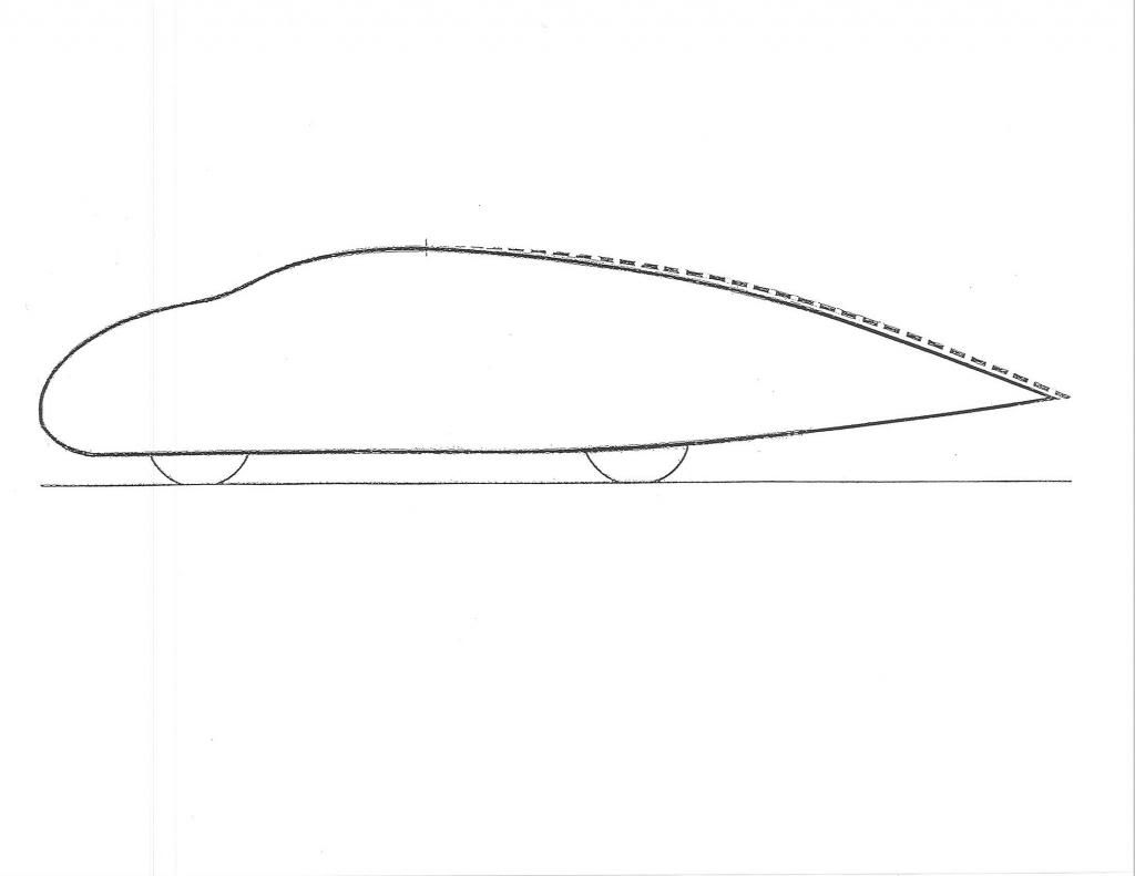
 *I think it was the 1929 ZMC 'tin bubble' metalclad airship which was built to one of these low ratios.It had very good speed for its power and frontal area but made the crew seasick,and you find airships built longer for flight stability.
 Here's the 'tin bubble' at the bottom
 
This image has been resized. Click this bar to view the full image. The original image is sized 791x1024.

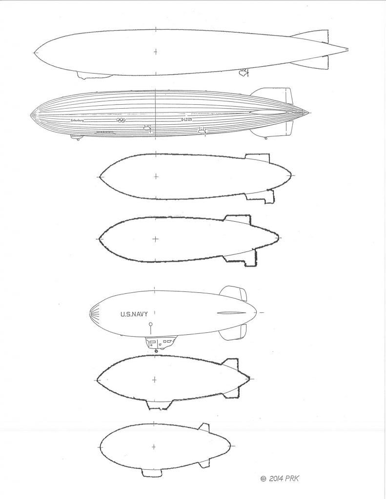
 *The 2.1 ratio is low drag,but for a bluff body it exceeds Mair's 22-degree contour slope maximum and also Buchheim et al's 23-degree slope maximum.
 *So as a half-body,in ground proximity,we need to stay near 22-23-degrees to protect the turbulent boundary layer from rapid pressure increases which trigger separation.
 -------------------------------------------------------------------------
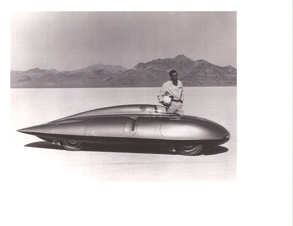
 *For struts and airfoil sections the bottom of the friction drag/pressure drag 'bucket' occurs at L/thickness= 3.92 (also from Hoerner).So for mirror stalks,suspension fairings,wheel fairings,etc.. Also,we find that 3.92:1 has also been used successfully on record cars with plan-taper of the body only.The 1957 MG EX 181 uses it.
 
This image has been resized. Click this bar to view the full image. The original image is sized 1024x791.

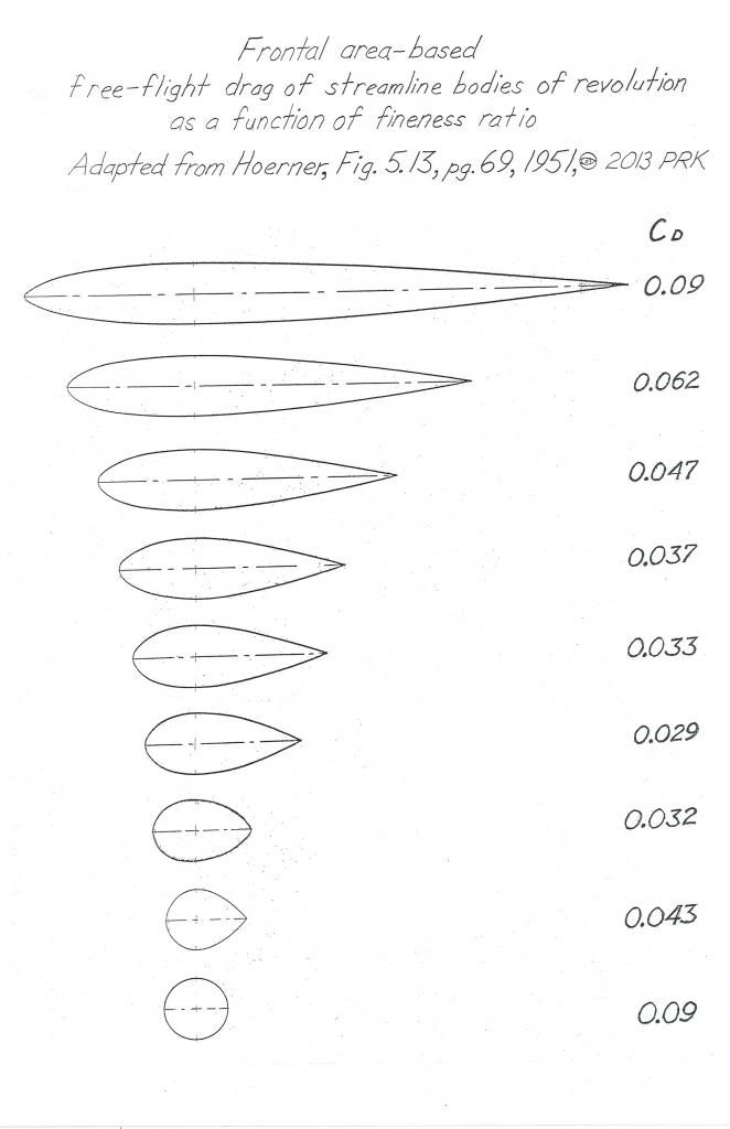
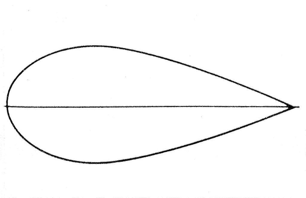
 Here's the 'template',4th from bottom
 
This image has been resized. Click this bar to view the full image. The original image is sized 662x1024.

 Here is the strut/wing section research,published by Horner,from Goldsein's research
 
This image has been resized. Click this bar to view the full image. The original image is sized 1000x773.

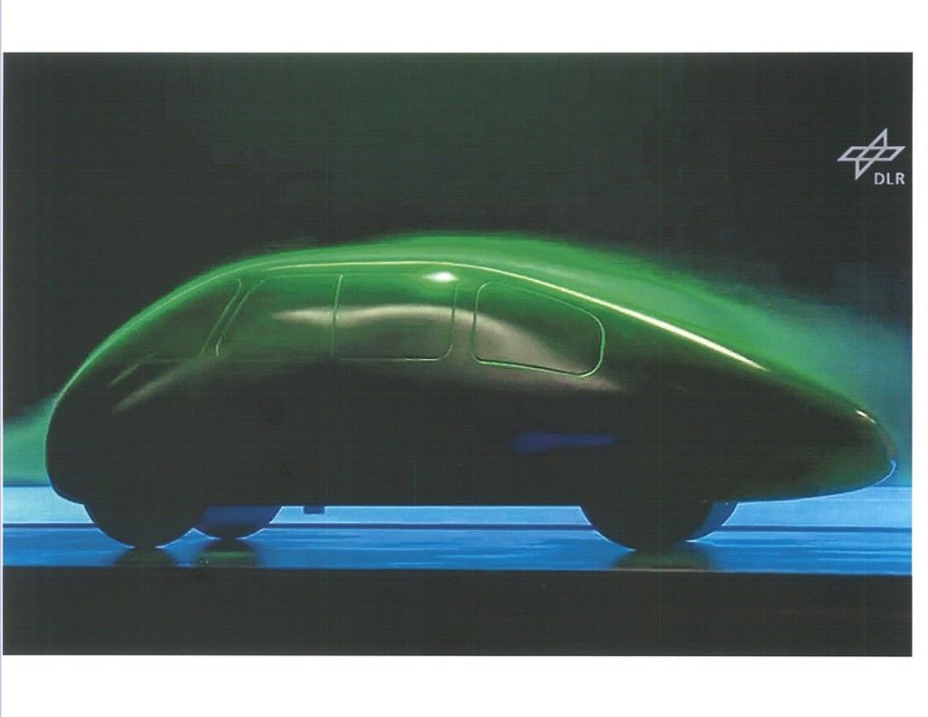
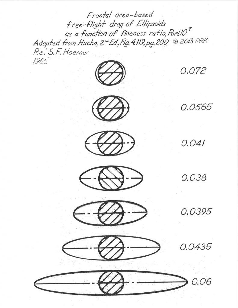
 Also,we could theoretically use elliptical bodies of revolution as a basis of automobile bodies as their drag behaves exactly the same as streamline bodies EXCEPT that the windshields would be too steep to see out of,so we default to the 'bulbous','bug' nose equally low drag to get something we can see out of with glass.Hucho used the elliptical body L/D ratios in his drag example of the 1966 VW Beetle 1300,which again,show the drag minimum @ 2.5:1.
 
This image has been resized. Click this bar to view the full image. The original image is sized 791x1024.

 On the Aerodynamic Streamlining Template-II I used a 'faster' rear contour,closer to Buchheim et al.'s,from my college fluid dynamics text.It's close to a 2.5:1 L/D streamline body also,just a little more aggressive early in the contour,then actually more conservative at the end,with 21-degrees maximum slope.
 
This image has been resized. Click this bar to view the full image. The original image is sized 1023x662.

 Here is the Buchheim et al. contour,developed in the VW wind tunnel.We shouldn't do anything more aggressive than this or we lose the game.
 
This image has been resized. Click this bar to view the full image. The original image is sized 1024x791.

 I kept the 'Template' conservative,as members are looking at maybe 800-man-hours to create an aft-body modification,and after all that you sure don't want to see separation back there.
 
This image has been resized. Click this bar to view the full image. The original image is sized 1024x791.


If there are no dogs in Heaven, then when I die I want to go where they go...

Offline Tom H

  • Beta testers
  • ***
  • Posts: 387
  • Total likes: 73
  • Built/flew LEU, built/flying DE
  • OS:
  • Windows Vista/Server 2008 Windows Vista/Server 2008
  • Browser:
  • Firefox 47.0 Firefox 47.0
  • Eagle Type: DE, LEU
Whoa!!!!!  You boys are getting way off subject with all the aero. talk.  I had hoped to get some other DE flyers to chime in with their flying experiences, especially concerning the payload capability and real-world flying of the DE or Cabin DE.

Hey Dan, being that you are a mod, would it be reasonable to suggest that you move some of this to another thread on the theory/application of aerodynamics?  I find it very interesting and informative, but a bit of a hi-jack, if I could be so bold.

Come on DE flyers, let's hear of your experiences!!!

Tom H
Tom H
Stubby, a BDE
Treehugger, LEU

Offline rfeenstra

  • 2017 Donor
  • *
  • Posts: 134
  • Total likes: 19
  • CabinBuilder
  • OS:
  • Windows NT 10.0 Windows NT 10.0
  • Browser:
  • Chrome 52.0.2743.116 Chrome 52.0.2743.116
  • Eagle Type: DE w/Cabin Mod
Dan, very interesting but probably difficult to apply all of it to my DE.  I'm just gonna do what looks OK and live with the results.  That will probably be some degree better that what is now!  However, if I ever design from scratch...

Thanks for the input!!

Offline Dan_

  • Staff
  • *
  • Posts: 1088
  • Total likes: 297
  • OS:
  • Windows NT 10.0 Windows NT 10.0
  • Browser:
  • Firefox 48.0 Firefox 48.0
  • Eagle Type: Legal Eagle
Dan, very interesting but probably difficult to apply all of it to my DE.  I'm just gonna do what looks OK and live with the results.  That will probably be some degree better that what is now!  However, if I ever design from scratch...

Thanks for the input!!
10-4...

I think you would find the Champ or Chief very close to the streamline.  Most likely no separation to speak of, and certainly no big burble to pull around with you.

The  Tailwind fuselage is arguably a lifting body.  It does suffer from small vortices off the square edges of the windshield and some separation on the bottom (from not following the teardrop shape) according to the late great August Raspet.  No airplane is perfect in all respects of course, each designer optimizing one thing or the other.


If there are no dogs in Heaven, then when I die I want to go where they go...

Offline rfeenstra

  • 2017 Donor
  • *
  • Posts: 134
  • Total likes: 19
  • CabinBuilder
  • OS:
  • Windows NT 10.0 Windows NT 10.0
  • Browser:
  • Chrome 52.0.2743.116 Chrome 52.0.2743.116
  • Eagle Type: DE w/Cabin Mod
Very true.  Most things are a compromise.  I'm not looking for speed, just to smooth the air past the tail and to try and remove some lead.

Offline Tom H

  • Beta testers
  • ***
  • Posts: 387
  • Total likes: 73
  • Built/flew LEU, built/flying DE
  • OS:
  • Windows Vista/Server 2008 Windows Vista/Server 2008
  • Browser:
  • Firefox 47.0 Firefox 47.0
  • Eagle Type: DE, LEU
Dan, that aero info is very informative.  I've seen most of it before, but not in one place like this.

I knew that there was a huge difference in drag going from round profile to a streamline profile.  But, I am a bit surprised to see that going from round to angled square caused a drag increase.  Seeing how the fineness ratio changes the drag from bad to good and back to bad is interesting.  Good stuff.
Tom H
Stubby, a BDE
Treehugger, LEU

Offline Dan_

  • Staff
  • *
  • Posts: 1088
  • Total likes: 297
  • OS:
  • Windows NT 10.0 Windows NT 10.0
  • Browser:
  • Firefox 48.0 Firefox 48.0
  • Eagle Type: Legal Eagle
Dan, that aero info is very informative.  I've seen most of it before, but not in one place like this.

I knew that there was a huge difference in drag going from round profile to a streamline profile.  But, I am a bit surprised to see that going from round to angled square caused a drag increase.  Seeing how the fineness ratio changes the drag from bad to good and back to bad is interesting.  Good stuff.

The half sphere being lower than the full sphere is damnamazing... 

I guess it is like the tailgate up is lower drag than having it down.


If there are no dogs in Heaven, then when I die I want to go where they go...

Offline MrG

  • Full Member
  • ***
  • Posts: 193
  • Total likes: 12
  • Builder - Pilot
  • OS:
  • Windows 7/Server 2008 R2 Windows 7/Server 2008 R2
  • Browser:
  • Chrome 55.0.2883.87 Chrome 55.0.2883.87
  • Eagle Type: DE E-77
@rfeensta
love to see photos as you go and the numbers after you finish - you should reduce a fair bit of drag  from things ive done  
waiting to see what happens  -  want to do same thing
MrG
Temora Airport  Australia
1st Aussie DE built/flown
19-8866
-----------------------------
1 Oct 2015 First Flight
Feb 2019 - 155 hrs Flown
March 4th removed from service for Cabin Mods

Offline rfeenstra

  • 2017 Donor
  • *
  • Posts: 134
  • Total likes: 19
  • CabinBuilder
  • OS:
  • Windows NT 10.0 Windows NT 10.0
  • Browser:
  • Chrome 55.0.2883.87 Chrome 55.0.2883.87
  • Eagle Type: DE w/Cabin Mod
I'll be starting soon.  Getting ready to pull the wings off.  I will take pics as I go.

Offline Dave Stroud

  • Dave Stroud
  • Full Member
  • ***
  • Posts: 129
  • Total likes: 7
  • New Member
  • OS:
  • Windows 7/Server 2008 R2 Windows 7/Server 2008 R2
  • Browser:
  • Chrome 55.0.2883.87 Chrome 55.0.2883.87
  • Eagle Type: XL
Very interesting subject. I just did a google search for some flying examples. For our speed ranges, the Sorrell Guppy and Hiperlight had quite interesting streamline shapes.  I think one of them first flew with a Cushman 18 hp golf cart engine.
Dave Stroud
Ottawa, Canada

Offline Dan_

  • Staff
  • *
  • Posts: 1088
  • Total likes: 297
  • OS:
  • Windows NT 10.0 Windows NT 10.0
  • Browser:
  • Firefox 50.0 Firefox 50.0
  • Eagle Type: Legal Eagle
Leonard built a Guppy back in the day.  It may very well be what got him interested in cutting down the Volkswagen engine.


If there are no dogs in Heaven, then when I die I want to go where they go...


EaglersNest Mission Statement:
To maintain the comprehensive searchable database resource for Builders and Fliers of Leonard Milholland ultralight airplane designs aka Legal Eagle Ultralights.

BetterHalfVW.com  becomes LegalEagleAirplane.com - stay in contact with Leonard and get plans for all the Milholland Designs at LegalEagleAirplane.com
SimplePortal 2.3.7 © 2008-2024, SimplePortal